Understanding the 2:1 Joint Design Ratio
Why ASTM C1193 mandates a 2:1 width-to-depth relationship for expansion joints and how depth controls internal cohesive and adhesive stress.
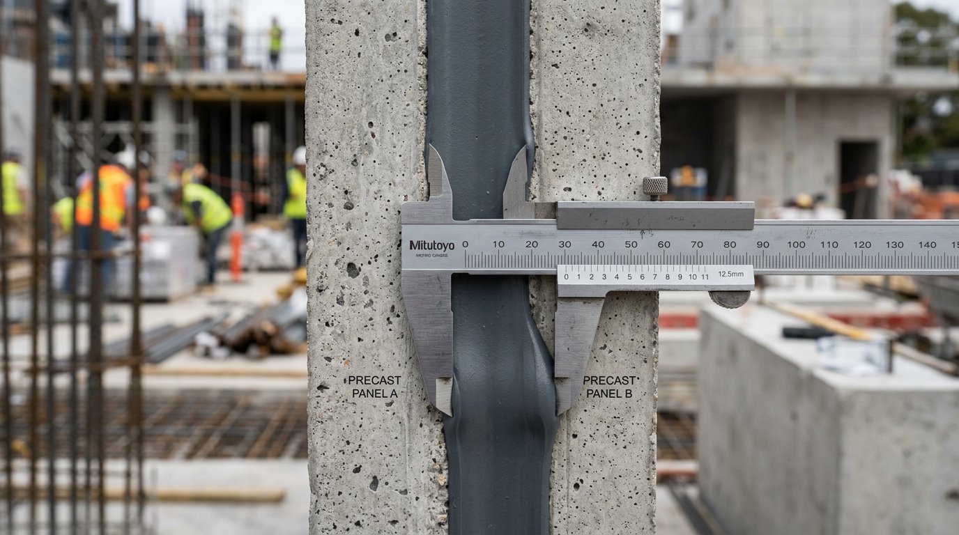
In architectural building envelopes, movement joints are designed to perform a demanding structural mission: they must remain watertight, airtight, and structurally sound while expanding and contracting across decades of thermal cycling, wind sway, and seismic vibration.
Yet, building forensic audits reveal that over 70% of premature joint sealant failures occur not because the chemical product was defective, but because the joint was improperly engineered. Specifically, installing a sealant too deep is the single most common cause of catastrophic cohesive rupture.
Major international engineering standards—including ASTM C1193 (Standard Guide for Use of Joint Sealants), ASTM C1472 (Standard Guide for Calculating Movement and Other Joint Widths), and ISO 11600—unanimously specify the 2:1 Width-to-Depth Ratio as the foundational geometry for dynamic expansion joints.
In this technical guide, we examine the structural biomechanics of elastomeric joints, derive the finite element physics of the hourglass profile, calculate thermal movement sizing, diagnose failure modes, and outline proper dry-tooling protocols.
1. The Physics of Elastomeric Movement: Why Depth Matters
To understand why depth governs sealant longevity, one must grasp how elastomeric materials behave under tension. Cured architectural sealants (silicones, polyurethanes, and polysulfides) are virtually incompressible elastomers with a Poisson’s ratio (ν) close to 0.5.
ν = -\frac{ε_transverse}{ε_axial} ≈ 0.5This means that when a sealant bead is pulled in tension across a widening gap, its total volume remains strictly constant. Because volume cannot change, the sealant must contract (neck inward) from its top and bottom unbonded surfaces.
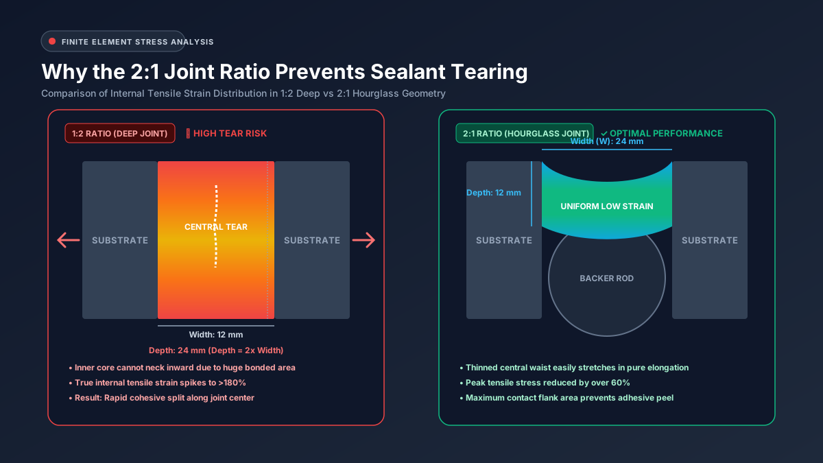
Figure 1: Finite Element Analysis (FEA) strain distribution comparison: a deep 1:2 joint (left) locks the material core, causing localized strain spikes >180%, while a 2:1 hourglass joint (right) distributes tensile strain uniformly.
The Problem with Deep Joints (1:1 and 1:2 Ratios)
Consider what happens when an installer fills a 12 mm wide by 24 mm deep joint cavity completely with sealant:
- Restricted Necking: The huge contact area along the vertical substrate walls (
24 mmon each side) anchors the material firmly to the structure. - Triaxial Stress Concentration: Because the inner core of the sealant is physically restrained by the massive bonded flanks, it cannot neck inward to relieve strain.
- Severe Localized Strains: As the building panels contract in winter, opening the joint by just 25%, the internal true tensile strain at the joint core spikes to over 180% to 220%.
- Cohesive Centerline Rupture: The internal tensile stress exceeds the ultimate tensile strength of the polymer matrix, causing the sealant bead to split violently down its center line.
       DEEP JOINT (1:2 RATIO)                HOURGLASS JOINT (2:1 RATIO)
            WIDTH = 12mm                            WIDTH = 24mm
       +--------------------+                  +--------------------+
       |                    |                  \   Concave Face     /
       |                    |                   \                  /
DEPTH  |    HIGH STRESS     |  vs.       DEPTH   |   LOW STRESS     |  <-- Thinned
24mm   |     CORE (180%)    |            12mm    /   WAIST (25%)    \      waist stretches
       |                    |                   /   Convex Back    \      freely without
       |                    |                  +--------------------+      tearing
       +--------------------+                     (Backer Rod Bed)
         [Centerline Tear]                     [100,000+ Cycles Safe]
The Hourglass Solution (2:1 Ratio)
By contrast, when a 24 mm wide joint is configured with a depth of 12 mm over a round polyethylene backer rod:
- The thinned central waist has minimal mass resisting extension.
- The outer concave tooling and inner convex backer rod geometry allow both faces to neck inward smoothly in pure uniaxial tension.
- When the joint widens by 25%, the maximum true strain in the center waist remains under 30% to 35%, well within the elastic fatigue limit of high-performance architectural sealants.
2. Universal Architectural Joint Sizing Rules
While engineers must always consult product-specific Technical Data Sheets (TDS), the building envelope industry adheres to the following universal sizing matrix codified in ASTM C1193:
Joint Width (W) | Required Depth (D) | Width-to-Depth Ratio | Engineering Justification |
|---|---|---|---|
| < 6 mm (< 1/4 in) | Not Permitted | N/A | Unacceptable for exterior dynamic movement; cannot accommodate thermal movement without tearing. |
| 6 mm to 12 mm (1/4 to 1/2 in) | Equal to Width (6--12 mm) | 1:1 Ratio | Minimum 6 mm depth required to ensure adequate adhesive bite and contact area on substrate flanks. |
| 12 mm to 25 mm (1/2 to 1 in) | 1/2 of Width (6--12.5 mm) | 2:1 Ratio | Optimal configuration: minimizes internal tensile stresses while maintaining high bond contact area. |
| > 25 mm (> 1 in) | Cap at 12 mm to 15 mm | 2:1 to 3:1 Ratio | Exceeding 15 mm depth produces excessive mass, risking sagging, slump, and high internal shear forces. |
[!IMPORTANT] The 6 mm (1/4 in) Minimum Depth Rule: Regardless of how narrow a joint is, a dynamic exterior joint must never be shallower than 6 mm (1/4 in). If a joint is tooled at a depth of only 2 mm or 3 mm, wind pressure, hydrostatic water head, and substrate peeling forces will rip the thin membrane away from the substrate interface.
3. Calculating Joint Movement: Thermal Expansion Mechanics
Joint widths must not be arbitrarily picked off architectural elevations. They must be mathematically sized to accommodate the thermal expansion and contraction of adjacent cladding panels over seasonal extremes.
The linear thermal movement (Δ L) of a building panel is calculated using the Coefficient of Linear Thermal Expansion (α):
\Delta L = L × \alpha × \Delta TWhere:
L= Length of the cladding panel (distance between movement joints).α= Coefficient of Linear Thermal Expansion of the substrate material (10⁻⁶/°C).Δ T= Extreme temperature variation between maximum summer surface heat and minimum winter frost.
Thermal Expansion Coefficients of Common Substrates
| Substrate Material | Coefficient (α in 10⁻⁶/°C) | Movement per 10 m Panel (Δ T = 50°C) |
|---|---|---|
| Structural Aluminum | 23.0 × 10⁻⁶ / °C | 11.5 mm (0.45 in) |
| Dense Architectural Concrete | 11.0 × 10⁻⁶ / °C | 5.5 mm (0.22 in) |
| Structural Carbon Steel | 12.0 × 10⁻⁶ / °C | 6.0 mm (0.24 in) |
| Clay Brick Masonry | 6.0 × 10⁻⁶ / °C | 3.0 mm (0.12 in) |
| Glass (Float) | 9.0 × 10⁻⁶ / °C | 4.5 mm (0.18 in) |
Sizing the Nominal Joint Width (W)
Once expected movement (Δ L) is known, determine the required nominal joint width (W_n) based on the sealant’s ASTM C920 Movement Class (M):
W_n = (\Delta L / M) × Safety FactorFor example, if adjacent precast concrete panels produce 5 mm of total thermal movement, and you specify an ASTM C920 Class 25 (±25%) polyurethane sealant with an engineering safety factor of 1.5:
W_n = (5 mm / 0.25) × 1.5 = 30 mmTo maintain the optimal 2:1 ratio, the sealant depth over the backer rod must be set to 15 mm.
4. Diagnostic Forensics: The 3 Primary Joint Failure Modes
When an architectural joint fails, forensic engineers inspect the failed specimen under magnification to diagnose the root cause. All joint failures fall into three distinct classifications:
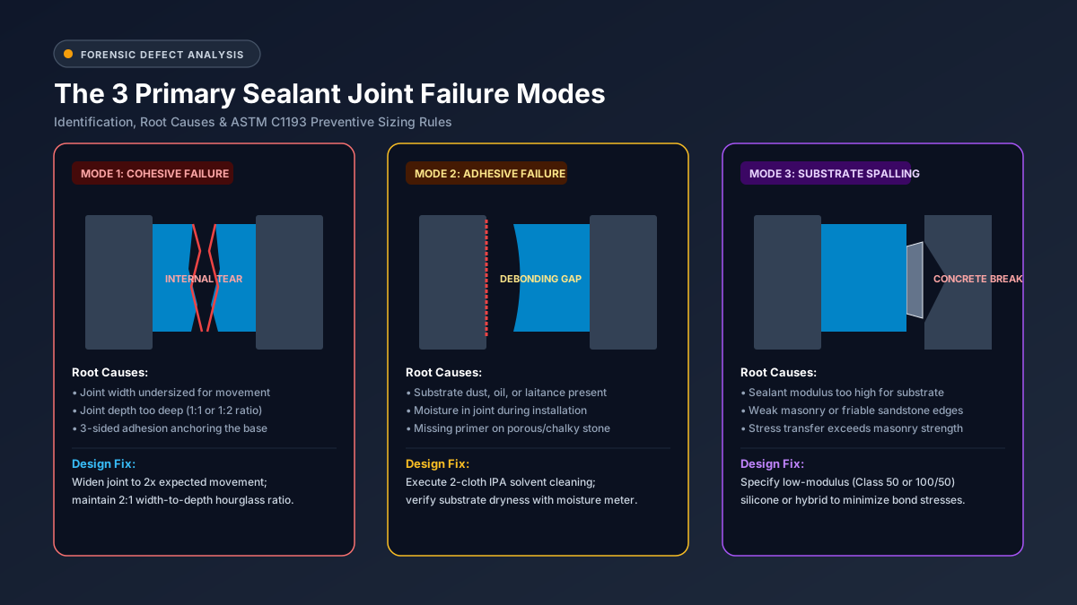
Figure 2: The three primary architectural joint failure modes: Cohesive internal tearing (left), Adhesive interface debonding (center), and Substrate spalling / substrate rupture (right).
Mode 1: Cohesive Failure (Internal Polymer Rupture)
- Symptom: Sealant remains firmly stuck to both substrate flanks, but splits wide open down the middle.
- Root Cause: Excessive joint movement exceeding product rating, installing the sealant too deep (
1:1or1:2ratio), or three-sided adhesion to the joint floor. - Correction: Install proper closed-cell backer rod to re-establish the 2:1 width-to-depth hourglass profile.
Mode 2: Adhesive Failure (Flank Debonding)
- Symptom: Sealant bead remains intact as an unbroken rubber strip, but peels clean away from one or both substrate walls.
- Root Cause: Contaminated substrate surface (dust, form-release oils, efflorescence, moisture, frost), lack of manufacturer-specified primer, or tooling with soapy water.
- Correction: Clean substrate flanks using the two-cloth solvent wipe technique (ASTM D412), prime porous masonry, and ensure substrates are 100% dry.
Mode 3: Substrate Spalling (Concrete/Masonry Edge Breakage)
- Symptom: The sealant adhesive bond remains unbroken, but chunks of the concrete or sandstone substrate break off with the sealant.
- Root Cause: Specifying a high-modulus sealant on weak masonry or friable stone. In cold weather, the sealant generates more tensile force than the concrete’s tensile rupture strength.
- Correction: Switch to an ultra-low modulus silicone (ASTM C920 Class 50 or 100/50) which exerts minimal stress on delicate masonry edges.
5. Tooling Protocols: Why You Must Never Use Soapy Water
A critical factor in achieving the 2:1 ratio is joint tooling. Tooling forces the extruded sealant paste firmly against the substrate flanks to eliminate air pockets, wets the microscopic pores, and sculpts the outer concave hourglass face.
However, a dangerous practice persists among inexperienced applicators: spraying soapy water or detergent onto uncured sealant to facilitate slicking.
                THE DANGERS OF SOAPY WATER TOOLING

   [❌ SOAPY WATER WET TOOLING]            [✓ DRY-TOOLING PROTOCOL]

   1. Detergent seeps between           1. Dry stainless steel spatula
      sealant and substrate,               forces paste firmly into pores.
      causing adhesive wash-out.
                                        2. 100% virgin chemical bond
   2. Traps surfactant layer,              intact with substrate flanks.
      causing delamination.
                                        3. No mold/mildew food source;
   3. Soaps contain phosphates;            clean, uniform hourglass
      promotes black mildew.               concavity.
The 3 Failures Caused by Wet Tooling:
- Adhesive Delamination: When soapy water is sprayed over a freshly gunned joint, the liquid runs ahead of the spatula and washes down the unbonded flank interfaces. The soap deposits a microscopic surfactant film that permanently destroys chemical adhesion.
- Polymer Discoloration & Leaching: Surfactants interfere with the moisture-curing reaction of neutral silicones and polyurethanes, leading to gummy, tacky skins that attract road grime.
- Biological Growth: Detergent residues contain organic compounds that act as food for black mildew and mold spores, ruining exterior aesthetics within 12 months.
The Professional Standard: Always dry-tool using contoured stainless steel spatulas, Teflon scrapers, or flexible polyurethane tooling spatulas lubricated exclusively with approved, non-staining tooling fluids specified by the sealant manufacturer.
6. Frequently Asked Questions (FAQ)
Why can’t I just fill the whole joint with sealant if it’s deep?
Filling a deep joint without a backer rod creates two disastrous problems:
- It creates three-sided adhesion, where the sealant sticks to the bottom floor as well as both walls, causing catastrophic shear tearing during movement.
- It increases the volume of material exponentially, creating severe internal tensile strains (>180%) that destroy cohesive integrity. Always install backer rod to maintain the 2:1 ratio.
What is the maximum joint width suitable for elastomeric sealants?
Standard elastomeric sealants can span expansion joints up to 50 mm (2 in) when engineered with proper 2:1 geometry and supported by oversized backer rods. For joint gaps exceeding 50 mm (such as bridge decks or seismic expansion seams), field-applied liquid sealants should be replaced with pre-compressed expanding foam tapes (EMSEAL) or mechanical architectural joint systems.
What is the difference between high-modulus and low-modulus sealant?
- High-Modulus Sealants: Require significant force to stretch. They are stiff and durable, making them ideal for high-traffic pedestrian floors, interior glazing, and structural glass.
- Low-Modulus Sealants: Stretch very easily under minimal force. They exert little pull on substrate flanks, making them mandatory for exterior precast concrete, brick masonry, and synthetic EIFS facades to prevent substrate spalling.
What should I do if a joint is only 4 mm wide?
A 4 mm joint cannot accommodate standard exterior thermal expansion without failing. You must either:
- Widen the joint using a concrete groover or diamond tuck-pointing saw to at least 6 mm to 10 mm.
- If widening is structurally prohibited, use a surface-applied preformed silicone transition tape (such as Dow Dowsil 123 Silicone Seal) bridged across the seam.
Why do some manufacturers recommend a 1:1 ratio for narrow joints?
For joints under 10 mm (3/8 in), adhering strictly to a 2:1 ratio would produce an ultra-thin depth of only 3 mm to 5 mm. A 3 mm sealant bead lacks sufficient cross-sectional area to withstand hydrostatic wind-driven rain and cannot provide enough contact surface area on the substrate flank to prevent peeling. Thus, standards mandate a 1:1 ratio with a 6 mm minimum depth for narrow joints.
Precision Sizing & Volume Estimation Tools
Ensure your architectural joints comply with ASTM C1193 specifications before ordering materials:
- Interactive Sealant Joint Calculator — Automatically checks width-to-depth ratios and calculates container requirements.
- Thermal Movement & Concrete Expansion Sizing — Compute panel expansion based on substrate material and thermal swings.
- Backer Rod Sizing Guide — Select closed-cell vs. open-cell rods for your specific project.