Preventing Three-Sided Joint Adhesion
Why three-sided adhesion causes rapid joint failure and how to select ASTM C1330 backer rods and bond-breaker tapes to preserve movement capability.
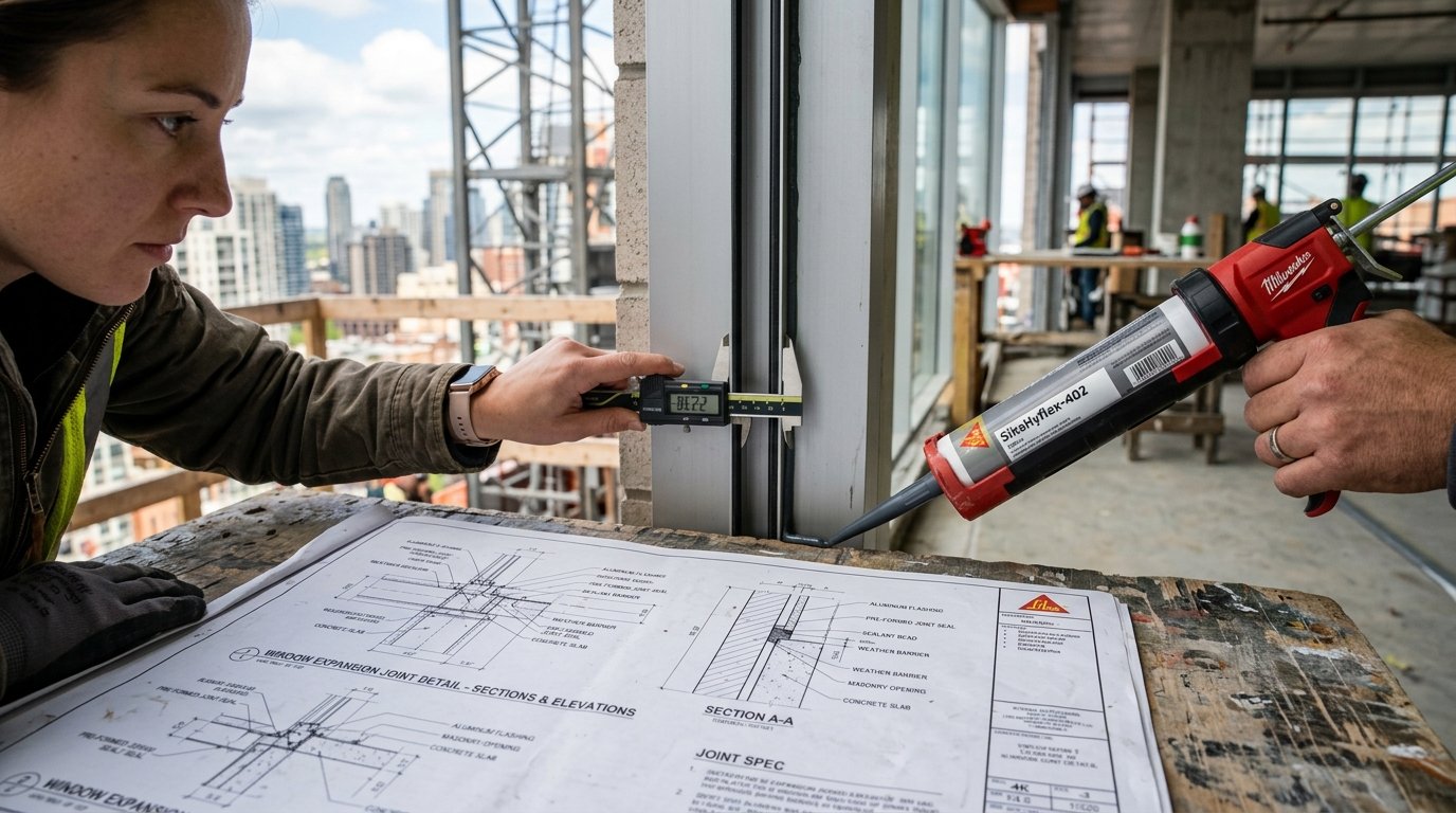
In the science of structural building joints, few design mistakes trigger faster or more devastating failures than three-sided adhesion. When an elastomeric sealant bonds to the bottom or base of a joint channel in addition to its two side walls, its movement capability drops by over 80%. The resulting triaxial tensile stresses quickly tear the sealant apart, leading to water intrusion, concrete rebar corrosion, and costly facade rehabilitation.
The primary engineering solution to three-sided adhesion is the correct specification and installation of joint backing materials—predominantly elastomeric backer rods conforming to ASTM C1330 (Standard Specification for Cylindrical Sealant Backing for Use with Cold Liquid-Applied Sealants) and specialized bond-breaker tapes.
In this comprehensive guide, we examine the mechanical physics of three-sided stress restraint, detail the four structural functions of backer rods, compare Closed-Cell vs. Open-Cell vs. Bi-Cellular chemistries, provide exact sizing matrices, explore bond-breaker tape protocols for shallow joints, and detail field installation best practices.
1. The Biomechanics of Three-Sided Adhesion Failure
To understand why bonding to a third surface causes failure, consider the mechanics of a working movement joint. In an ideal expansion joint, the sealant bridges two opposing substrates (Substrate A on the left and Substrate B on the right). When seasonal temperature drops cause the building panels to contract, the joint widens.
Because elastomeric sealants are incompressible materials (Poisson’s ratio ≈ 0.5), the sealant bead must neck inward from its top and bottom faces to maintain constant volume as it stretches.
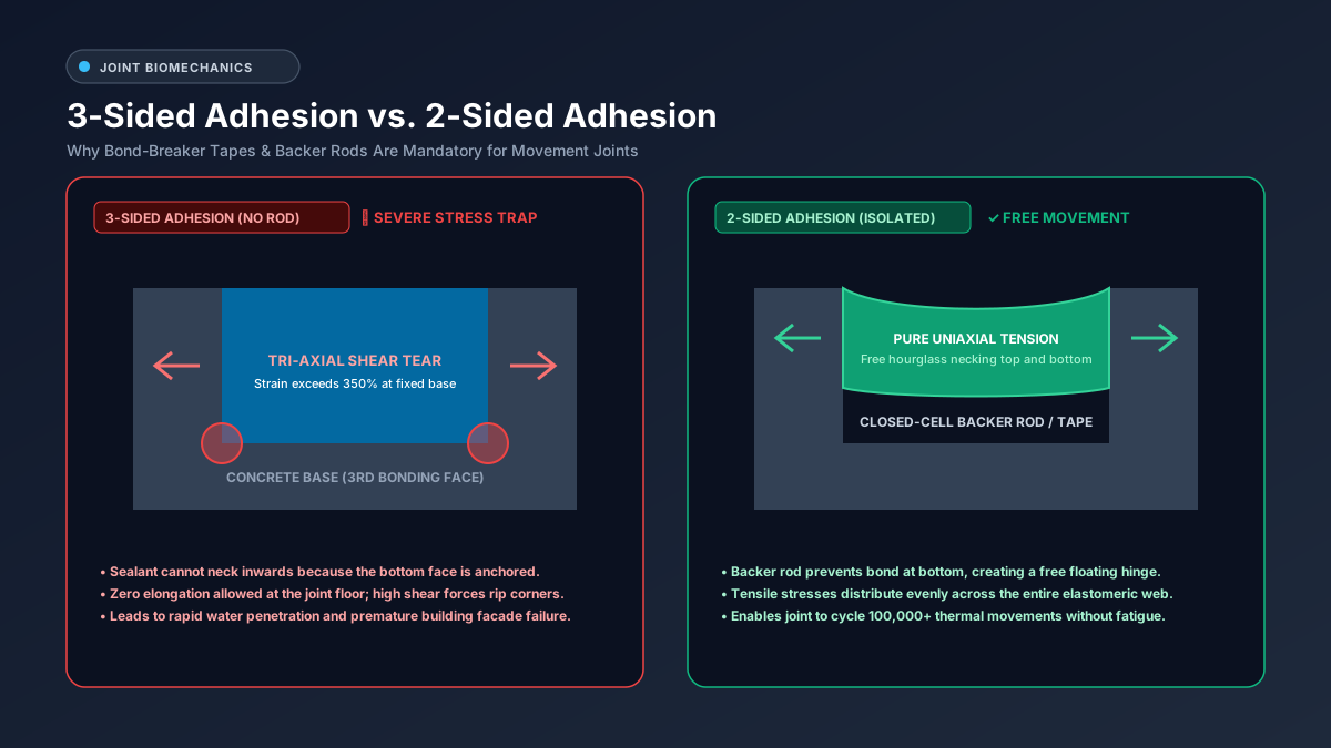
Figure 1: Joint biomechanics comparison: Three-sided adhesion (left) locks the joint floor, creating extreme shear tearing >350%, whereas two-sided adhesion (right) allows free hourglass necking and pure uniaxial tension.
What Happens in Three-Sided Adhesion?
When a joint is poured or gunned directly into an unbacked slot or against a rigid concrete trench floor:
- Bond Formation on Three Faces: The paste bonds aggressively to the left wall, the right wall, and the stationary concrete base.
- Restricted Basal Elongation: As the side walls pull apart, the sealant molecules at the bottom floor are physically anchored to the substrate. They have zero freedom to stretch or neck inward.
- Severe Triaxial Shear Stress: While the upper surface of the bead stretches in tension, the bottom interface is subjected to intense multi-directional tearing forces. Finite element models demonstrate that localized shear strain at the bottom corners spikes to over 350% to 450% under just 20% panel movement.
- Catastrophic Corner Tearing: The extreme localized stress initiates microscopic micro-tears at the bottom corner fillet, which rapidly propagate diagonally upward through the center of the bead, resulting in total cohesive rupture.
       THREE-SIDED ADHESION (FAIL)             TWO-SIDED ADHESION (PASS)
            SUBSTRATES PULL APART                 SUBSTRATES PULL APART
            <---             --->                 <---             --->
       +-----+                 +-----+       +-----+                 +-----+
       |     |   SEALANT       |     |       |     |   CONCAVE       |     |
       |     |   LOCKED        |     |       |     |    WAIST        |     |
       |     |   AT BASE       |     |       |     +-------. .-------+     |
       |     +--------.--------+     |       |       (BACKER ROD)          |
       |  ▲   CRACK PROPAGATES   ▲   |       |                             |
       +--┴----------------------┴---+       +-----------------------------+
          RIGID BASE (3RD BOND FACE)             FREE TO ELONGATE (NO BOND)
2. The 4 Essential Functions of Backer Rods
A common misconception in the field is that backer rods are merely cheap foam fillers intended to save money on expensive sealant. While material cost savings are substantial, backer rods perform four indispensable engineering roles:
- Acts as a Permanent Bond Breaker: Polyethylene and polyurethane foam backer rods are chemically formulated so that structural silicone, polyurethane, and polysulfide sealants will not adhere to them. This ensures that the bottom surface of the bead remains completely unconstrained and free to move.
- Regulates Sealant Depth (Enforcing 2:1 Ratio): Backer rods provide an exact physical stop, allowing the applicator to control sealant depth precisely according to ASTM C1193 2:1 joint design rules.
- Serves as a Tooling Anvil: When tooling a joint, the applicator must exert between 30 and 50 psi of forward pressure with a spatula to force the viscous paste into microscopic substrate pores and eliminate internal air pockets. The resilient foam backer rod provides the essential firm resistance needed for this pressure. Without a backer rod, tooling pressure simply pushes the wet paste deeper into the wall cavity.
- Forms the Parabolic Convex Back Surface: Because backer rods are cylindrical, their rounded top profile imparts a natural convex curve to the underside of the sealant bead. Combined with the concave curve tooled onto the exterior face, this produces the structurally optimal hourglass cross-section.
3. Backer Rod Material Types: ASTM C1330 Classification
Not all foam rods are created equal. ASTM C1330 classifies sealant backing rods into three distinct structural categories:
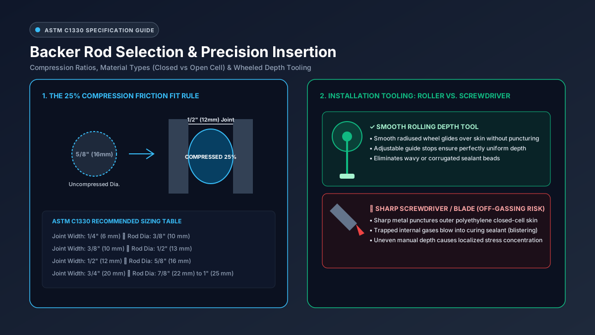
Figure 2: Backer rod engineering: The 25% compression friction-fit rule (left) and proper installation using a smooth wheeled depth-gauge roller tool versus destructive screwdriver punctures (right).
Type C: Closed-Cell Polyethylene Foam
- Structure: Extruded closed-cell low-density polyethylene (LDPE) with an impervious, non-absorbent smooth outer skin.
- Key Advantage: Zero water absorption. Impervious to moisture penetration, making it mandatory for horizontal exterior pavement, bridge decks, concrete flatwork, and wet-area facades.
- Critical Risk (Outgassing): If an installer punctures the outer skin during insertion with a screwdriver or utility knife, gases trapped inside the microscopic cells escape under pressure into the uncured sealant paste, creating large gas blisters and voids throughout the bead.
Type O: Open-Cell Polyurethane Foam
- Structure: Reticulated open-cell polyurethane foam with interconnected cellular porosity.
- Key Advantage: High compressibility & rapid cure. Can be compressed up to 70% without crushing cell structure. Its porous network allows atmospheric moisture to circulate freely behind the bead, significantly accelerating the cure rate of one-part moisture-curing polyurethanes and silicones. It cannot outgas or blister when cut.
- Critical Risk: Acts like a sponge. If water breaches the joint, open-cell foam can absorb and hold liquid against building substrates. Never use open-cell backing in horizontal traffic joints or below-grade waterproofing.
Type B: Bi-Cellular Polyethylene Foam
- Structure: An advanced hybrid consisting of a durable, water-resistant outer closed skin encasing a softer, highly compressible interior open-cell core.
- Key Advantage: The “best of both worlds.” It provides the water resistance of closed-cell foam combined with the puncture-proof outgassing immunity of open-cell foam. If punctured during installation, it will not blow gas bubbles into wet sealant. Highly recommended for dynamic curtain wall and window perimeter sealing.
ASTM C1330 Engineering Benchmark Matrix
| Performance Property | Type C (Closed-Cell PE) | Type O (Open-Cell PU) | Type B (Bi-Cellular) |
|---|---|---|---|
| Water Absorption (ASTM C1016) | < 0.03 g/cm³ (Impervious) | > 0.50 g/cm³ (Absorbent) | < 0.05 g/cm³ (Resistant) |
| Outgassing Blister Risk | High (If punctured) | Zero (Cannot outgas) | Zero to Low |
| Recommended Joint Location | Horizontal slabs, wet facades | Interior partitions, window heads | Precast panels, curtain walls |
| Temperature Resistance | -45°C to +70°C | -40°C to +90°C | -50°C to +80°C |
| Compression Deflection (25%) | 5 to 10 psi (Firm) | 1 to 3 psi (Very soft) | 3 to 6 psi (Moderate) |
4. Sizing Backer Rod: The 25% Compression Rule
A backer rod must be held securely in position solely by mechanical friction against the joint walls. If a rod is sized too small, it will displace during tooling, slipping deeper into the void or floating to the surface. If sized too large, it cannot be inserted without crushing the joint shoulders or tearing the foam skin.
The Standard Rule: Size 25% Larger than Joint Width
Always select a nominal backer rod diameter that is approximately 25% wider than the joint gap:
Rod Diameter = Joint Width × 1.25| Nominal Joint Width | Recommended Rod Diameter | Resulting Compression |
|---|---|---|
| 1/4 in (6 mm) | 3/8 in (10 mm) | 33% (Tight friction fit) |
| 3/8 in (10 mm) | 1/2 in (13 mm) | 25% (Optimal) |
| 1/2 in (12 mm) | 5/8 in (16 mm) | 25% (Optimal) |
| 3/4 in (20 mm) | 7/8 in (22 mm) to 1 in (25 mm) | 20% to 25% |
| 1 in (25 mm) | 1-1/4 in (32 mm) | 22% |
| 1-1/2 in (38 mm) | 2 in (50 mm) | 24% |
5. What About Shallow Joints? Bond-Breaker Tapes
On many construction sites, expansion joints are too shallow to accommodate even the smallest round backer rod. Examples include:
- Reglet joints in stone coping.
- Perimeter control seams over structural shelf angles.
- Expansion joints in thin ceramic tile or terrazzo beds.
- Curtain wall mullion splice covers with less than
8 mmof cavity clearance.
In these shallow geometries, installing a backer rod would reduce the sealant depth to less than 3 mm, guaranteeing immediate peeling.
The Solution: Self-Adhesive Bond-Breaker Tape
When depth is constrained, engineers specify a Pressure-Sensitive Bond-Breaker Tape applied directly across the joint floor.
                  SHALLOW JOINT WITH BOND-BREAKER TAPE

             SUBSTRATE A                          SUBSTRATE B
       +-----------------------+              +-----------------------+
       |                       |  SEALANT     |                       |
       |                       \  CONCAVE     /                       |
       |                        \  BEAD      /                        |
       |                         +----------+                         |
       |                  ========================                    |  <-- Polyethylene
       +------------------|  BOND-BREAKER TAPE   |--------------------+      tape adheres to base
                          +----------------------+                           but REJECTS sealant
                              RIGID JOINT FLOOR
Bond-Breaker Tape Requirements:
- Material Chemistry: Must be manufactured from virgin polyethylene (PE) or fluoropolymer (PTFE/Teflon) film with an aggressive acrylic adhesive on one side only.
- Non-Adherent Face: Sealants will not bond to the slick polyethylene outer film. The sealant adheres tenaciously to the side substrates while floating freely across the tape.
- Strict Prohibition on General Tapes: Never use duct tape, blue painter’s masking tape, or electrical vinyl tape. Sealants bond tenaciously to paper masking tape and PVC electrical backing, recreating the exact three-sided adhesion condition you are trying to avoid.
6. Field Installation Protocol: Tools & Inspection
Proper installation of backer rod is as critical as material selection. Follow this strict protocol verified by ASTM C1521 field inspection standards:
1. The Wheeled Depth Roller Tool (Never Use Screwdrivers)
Install backer rod using a smooth-wheeled rolling depth tool equipped with adjustable guide wheels.
- The radiused wheel presses the rod smoothly into the joint without stretching or abrading it.
- The depth collars ensure that the rod is set to the exact mathematical depth (e.g.,
10 mmbelow surface) along the entire linear run. - Strictly prohibit the use of sharp screwdrivers, putty knives, or trowel tips. Sharp edges puncture closed-cell skins and lead to catastrophic outgassing blistering.
2. Avoid Longitudinal Stretching
Never pull or stretch a foam backer rod during insertion. When stretched, the rod experiences elastic recovery after installation, contracting lengthwise and pulling itself out of the joint ends or tearing the uncured sealant bead above it. Always push the rod forward into the joint with a slight crowding action.
3. Splicing Techniques
When joining two rods, cut the ends square with a sharp razor. Butt the ends tightly together under slight axial compression. Do not overlap rods; overlapping creates an irregular bump that forces the sealant bead too thin at the lap.
7. Frequently Asked Questions (FAQ)
What happens if I puncture a closed-cell backer rod during installation?
Puncturing the closed skin with a sharp tool releases trapped blowing agents and atmospheric nitrogen into the joint cavity. As ambient temperatures rise, these gases expand and blow out into the uncured sealant paste above. This causes large blisters, cratered bubbles, and hollow tunnels throughout the sealant bead, completely destroying its waterproofing integrity. If a closed-cell rod is punctured, it must be removed and replaced.
Can I double up two small backer rods if I don’t have the right size on site?
No. Jamming two small backer rods into a joint side-by-side creates a cleft or valley between them. Sealant paste fills this cleft, creating a thick wedge of material that concentrates stresses and promotes tearing. Always keep standard industrial diameters (3/8”, 1/2”, 5/8”, 7/8”, 1”) stocked on the job site.
Can I use sand or polystyrene foam (Styrofoam) as a backer in concrete joints?
No. Silica sand shifts, settles, and provides no firm backing for tooling pressure. Expanded polystyrene (EPS / Styrofoam) is rigid, crushes under thermal movement, and melts when exposed to solvents in polyurethane primers. Furthermore, sealants bond aggressively to polystyrene, creating three-sided adhesion.
How do I inspect an installed backer rod before caulking?
Use a stepped depth gauge or digital caliper to check that the depth from the substrate face to the crown of the rod is consistent along the run. Perform a light finger tap test; the rod should feel firmly wedged against both flanks without sliding or rolling. Verify that no skin punctures, tears, or longitudinal twists are present.
How does ASTM C1521 field pull testing verify joint adhesion?
ASTM C1521 specifies a destructive field adhesion test: an inspector cuts a 3-inch section of the cured sealant bead free from the joint, grasps the flap, and pulls it at a 90-degree angle until failure occurs. If the backer rod performed its function, the sealant will stretch cleanly away from the backing foam and fail cohesively within the polymer, demonstrating that the bond to the side substrate is stronger than the material itself.
Interactive Joint Sizing & Material Tools
Eliminate guesswork and ensure your expansion joints comply with ASTM C1330 backing standards:
- Sealant Coverage & Volume Calculator — Accurately calculate joint volume and cartridge requirements.
- Understanding the 2:1 Joint Design Ratio — Why depth controls internal cohesive strain.
- Silicone vs Polyurethane Chemical Comparison — Selecting the right polymer for your backer rod assembly.